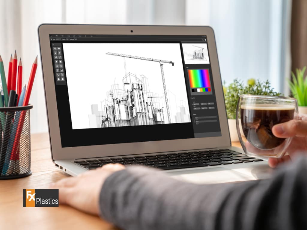
Computer Aided Drawing (CAD) is a powerful tool that has revolutionised the way designers, architects, engineers, and manufacturers create and produce their work. By leveraging digital technology, CAD allows users to create precise drawings and models that can be easily modified, shared, and utilised in various stages of the design and production process. From simple 2D sketches to complex 3D models, CAD has become an indispensable part of modern design and manufacturing.
In the context of manufacturing, Computer Aided Drawing (CAD) plays a crucial role in CNC routing and machining. These processes rely on the accuracy and detail provided by CAD to guide machines in cutting, shaping, and assembling materials. Understanding the basics of CAD is essential not only for creating detailed designs but also for ensuring that these designs can be effectively translated into physical products through CNC machining. Whether you’re just starting in the field of design or looking to enhance your skills, mastering CAD is a vital step toward achieving professional success.
Getting Started: Essential Tools and Software for CAD
Choosing the Right CAD Software:
When starting with Computer Aided Drawing (CAD), one of the first decisions you’ll need to make is selecting the right software. There are many CAD programs available, each with its strengths, weaknesses, and areas of specialisation. For beginners, it’s important to choose software that is user-friendly while still offering robust features that will allow you to grow as you gain more experience.
Some popular CAD software options include AutoCAD, SolidWorks, and Fusion 360. AutoCAD is widely used for architectural and engineering drawings, known for its precise 2D drafting capabilities. SolidWorks, on the other hand, is favoured in the engineering and manufacturing sectors for its strong 3D modeling features. Fusion 360 combines CAD, CAM (Computer Aided Manufacturing), and CAE (Computer Aided Engineering) tools, making it ideal for those interested in CNC routing and machining.
Basic Tools and Commands in CAD:
Once you’ve selected your CAD software, the next step is familiarising yourself with the basic tools and commands that form the foundation of Computer Aided Drawing (CAD). These tools allow you to create, modify, and organise your drawings and models effectively.
Key tools and commands in most CAD software include:
- Line and Shape Tools: Used to create basic geometric shapes like lines, circles, and rectangles, which are the building blocks of more complex designs.
- Dimensioning Tools: Allow you to accurately measure and label the dimensions of your drawings, ensuring precision.
- Layer Management: Helps organise different elements of your drawing by separating them into layers, making it easier to work on specific parts of the design without affecting others.
- Snap and Grid Features: Aid in aligning objects precisely by snapping them to grid lines or specific points.
Learning the Fundamentals: Core Concepts in CAD
Understanding the CAD Interface:
The interface of Computer Aided Drawing (CAD) software can seem overwhelming at first, but understanding its layout and functions is key to working efficiently. Most CAD interfaces are designed to be intuitive, with tools and options organised into toolbars, menus, and panels that are easily accessible.
In a typical CAD interface, you’ll find:
- Drawing Area: The central workspace where you create and modify your designs.
- Toolbars: Located around the drawing area, these contain the most commonly used tools and commands.
- Command Line (if applicable): Allows for text-based input of commands, providing an alternative to using the toolbar buttons.
- Properties Panel: Displays detailed information about the selected objects, allowing you to adjust their attributes.
- Layer Panel: Helps you manage the different layers of your drawing, making it easier to keep complex designs organised.
Introduction to CNC Routing and Machining:
Understanding the connection between Computer Aided Drawing (CAD) and CNC routing and machining is crucial for those looking to apply their CAD skills in manufacturing. CNC (Computer Numerical Control) machines use digital designs created in CAD software to guide their movements, allowing for precise cutting, drilling, and shaping of materials.
In a typical workflow, a designer creates a detailed 2D or 3D model using CAD software. This model is then converted into a format that a CNC machine can interpret, often involving a CAM (Computer Aided Manufacturing) process. The CNC machine follows the instructions derived from the CAD model, ensuring that the physical product matches the designer’s specifications with high accuracy.
This relationship between CAD and CNC machining is what allows for the production of complex parts and components with minimal human intervention. For those working in design, engineering, or manufacturing, mastering both Computer Aided Drawing (CAD) and CNC routing and machining is essential for creating high-quality, precise products.
Step-by-Step Tutorials: Building Your First CAD Project
Creating Basic 2D Drawings:
As you begin your journey in Computer Aided Drawing (CAD), one of the first projects you’ll likely tackle is creating basic 2D drawings. These foundational skills are essential for any CAD user, as they form the basis for more complex designs and models. In this section, we’ll walk you through a step-by-step tutorial to create a simple 2D drawing, guiding you through each stage of the process.
Step 1: Setting Up Your Drawing Environment
- Start by opening your CAD software and setting up your workspace. This includes selecting the appropriate units of measurement (millimeters, inches, etc.) and configuring your grid and snap settings for precision.
Step 2: Drawing Basic Shapes
- Use the line and shape tools to create the basic geometry of your design. For example, if you’re designing a simple mechanical part, you might start with a rectangle for the main body and add circles or lines to represent holes or other features.
Step 3: Adding Dimensions
- Once your basic shapes are in place, use the dimensioning tools to accurately measure and label each element of your drawing. This is crucial for ensuring that your design can be accurately manufactured, especially if it will be used in CNC routing and machining.
Step 4: Organising Layers
- To keep your drawing organised, place different elements on separate layers. For example, you might have one layer for the outlines, another for dimensions, and a third for any annotations or notes. This makes it easier to modify or update specific parts of your drawing without affecting the rest.
Step 5: Saving and Exporting Your Drawing
- Once your drawing is complete, save your work in the native CAD format. Additionally, you may need to export the file in a format compatible with CNC routing and machining (such as DXF or DWG), depending on the next steps in your project.
Transitioning to 3D Modeling:
After mastering 2D drawings, the next logical step in your Computer Aided Drawing (CAD) journey is to explore 3D modeling. 3D models are essential in many industries, particularly in engineering, architecture, and product design, where they provide a more comprehensive representation of an object.
Step 1: Creating a Simple 3D Model
- Begin by selecting a basic shape in your CAD software, such as a cube or cylinder. You can extrude, revolve, or loft 2D sketches to create these 3D forms. For example, if you drew a circle in 2D, you could extrude it into a cylinder in 3D.
Step 2: Adding Features
- Use tools like fillet, chamfer, and shell to add more complex features to your 3D model. These tools allow you to round edges, create bevels, or hollow out sections of your model, which can be critical for the final design.
Step 3: Applying Materials and Textures
- Many CAD programs allow you to apply materials and textures to your 3D models, giving you a more realistic preview of how the final product will look. This is especially useful in visualizing how different materials might perform in CNC routing and machining.
Step 4: Checking for Errors
- Before moving forward with manufacturing, it’s essential to check your 3D model for errors or inconsistencies. Most CAD software includes tools to validate the model, ensuring it’s ready for CNC routing and machining.
Step 5: Exporting for CNC Machining
- Finally, export your 3D model in a format compatible with CNC machines, such as STL or STEP files. These files will guide the CNC machine in producing your design with the precision required for manufacturing.
Common Challenges for CAD Beginners and How to Overcome Them
Avoiding Common Mistakes
As with any new skill, learning Computer Aided Drawing (CAD) comes with its set of challenges. Understanding and avoiding common mistakes can significantly smooth your learning curve and improve the quality of your work.
1. Over-complicating Early Projects
- Mistake: Beginners often dive into complex projects too soon, leading to frustration and errors.
- Solution: Start with simple designs and gradually increase the complexity as you become more comfortable with the tools and commands. Focus on mastering the basics before tackling intricate projects.
2. Ignoring Proper Dimensioning
- Mistake: Skipping or inaccurately applying dimensions can lead to designs that are unusable in real-world applications, especially in CNC routing and machining.
- Solution: Always apply precise dimensions to your drawings. Use the dimensioning tools available in your CAD software and double-check measurements to ensure accuracy.
3. Poor Layer Management
- Mistake: Failing to organise your work into layers can make your designs cluttered and difficult to modify.
- Solution: Use layers effectively to separate different elements of your design. For instance, keep outlines, dimensions, and annotations on separate layers. This will make it easier to manage and edit your drawings.
4. Not Saving Work Frequently
- Mistake: Forgetting to save your work regularly can result in the loss of hours of progress, especially if the software crashes.
- Solution: Make it a habit to save your work frequently. Most CAD software also allows you to set up auto-save intervals, ensuring your work is automatically saved at regular intervals.
5. Overlooking File Formats
- Mistake: Using the wrong file format can lead to compatibility issues when exporting designs for CNC routing and machining.
- Solution: Always ensure you’re exporting your drawings and models in the correct format required for the next stage of the process. Common formats for CNC machining include DXF, DWG, STL, and STEP.
Troubleshooting Basic Issues
When working with Computer Aided Drawing (CAD), you may encounter some technical challenges. Here are solutions to a few common issues:
1. Software Crashes or Freezes
- Issue: CAD software can sometimes crash or freeze, particularly when handling large or complex files.
- Solution: Ensure your computer meets the software’s system requirements. Close other programs to free up resources, and regularly update your software to the latest version. If a crash occurs, try opening the auto-saved version of your file.
2. Slow Performance
- Issue: CAD software may run slowly, especially when working with detailed 3D models.
- Solution: Reduce the level of detail displayed in the viewport by adjusting the software’s graphics settings. You can also simplify the model by hiding unnecessary layers or using lower resolution for textures during the design phase.
3. Difficulty Snapping to Grid or Objects
- Issue: Precision is crucial in CAD, but sometimes the snapping feature doesn’t work as expected.
- Solution: Check your snap settings to ensure they are properly configured. Adjust the grid spacing and make sure the snap function is enabled in the software’s settings.
4. Misaligned Objects or Dimensions
- Issue: Objects or dimensions may not align correctly, leading to inaccuracies.
- Solution: Use the alignment tools provided by the software, such as “Align” or “Distribute,” to ensure elements are perfectly aligned. Double-check dimensions and use the “Ortho” mode for straight lines.
5. File Corruption
- Issue: Occasionally, CAD files may become corrupted and unreadable.
- Solution: Always maintain backup copies of your work. If a file becomes corrupted, try opening it in a different version of the CAD software or using recovery tools if available.
Resources for Continuous Learning: Where to Go Next
Online Courses and Tutorials
As you continue your journey in Computer Aided Drawing (CAD), taking advantage of online resources can help deepen your understanding and improve your skills. Here are some reputable platforms and courses to consider:
1. Coursera
- What it Offers: Comprehensive CAD courses from top universities and institutions, covering everything from basic tools to advanced modeling techniques.
- Recommended Course: “Introduction to CAD, CAM, and Practical CNC Machining” which provides an excellent foundation in both CAD and its application in CNC routing and machining.
2. Udemy
- What it Offers: A wide range of CAD courses for different skill levels and software platforms.
- Recommended Course: “AutoCAD 2024 – Complete Beginners Course” which is great for those new to CAD, offering step-by-step instructions.
3. LinkedIn Learning
- What it Offers: Short courses and tutorials on specific CAD skills, ideal for continuous learning.
- Recommended Course: “CAD and Digital Manufacturing” which covers the integration of CAD with CNC routing and machining.
4. YouTube
- What it Offers: Free tutorials and walkthroughs from experienced CAD users, perfect for quick tips and specific techniques.
- Recommended Channels: “NYC CNC” for insights on CAD in machining and “CAD in Black” for detailed AutoCAD tutorials.
Exploring Advanced CAD Features
Once you’ve mastered the basics of Computer Aided Drawing (CAD), it’s time to explore more advanced features that can enhance your work, particularly those that are relevant to CNC routing and machining.
1. Parametric Modeling
- What It Is: A feature that allows you to create designs that automatically adjust based on specified parameters.
- Why It’s Important: Parametric modeling is crucial for designing parts that need to change size or shape depending on specific requirements, making it highly useful in manufacturing.
2. Assembly Modeling
- What It Is: A process of creating complex models by assembling individual components.
- Why It’s Important: Understanding assembly modeling is key for those working in product design and manufacturing, as it allows you to see how different parts fit together.
3. Simulation and Analysis
- What It Is: Tools within CAD software that simulate how your design will perform under real-world conditions.
- Why It’s Important: This feature helps you identify potential weaknesses in your design before production, saving time and resources.
4. Integration with CNC Machines
- What It Is: The ability to export CAD designs into formats that can be used directly by CNC machines.
- Why It’s Important: Understanding this integration is essential for those involved in CNC routing and machining, as it ensures your designs are accurately translated into physical products.


